
Design Challenge: Using an RGB LED, create a lighting controller with faders for changing brightness and color channels, on-off switch, and a control feature to interrupt the fade.
Stand P-UP, Creating a Lighting Controller for a Toy (Poodle) Sized Stage from Angela at ITP on Vimeo.
The Lighting Controller
Stand P-UP is a lighting board-stage combination built to the scale of a toy poodle, to be used for his on stage adventures. The lighting controller is designed as a small-scale theatrical lighting controller where sliders can fade colors in and out, one master control can fade them all, and an on-off switch can shut on and off the entire board.
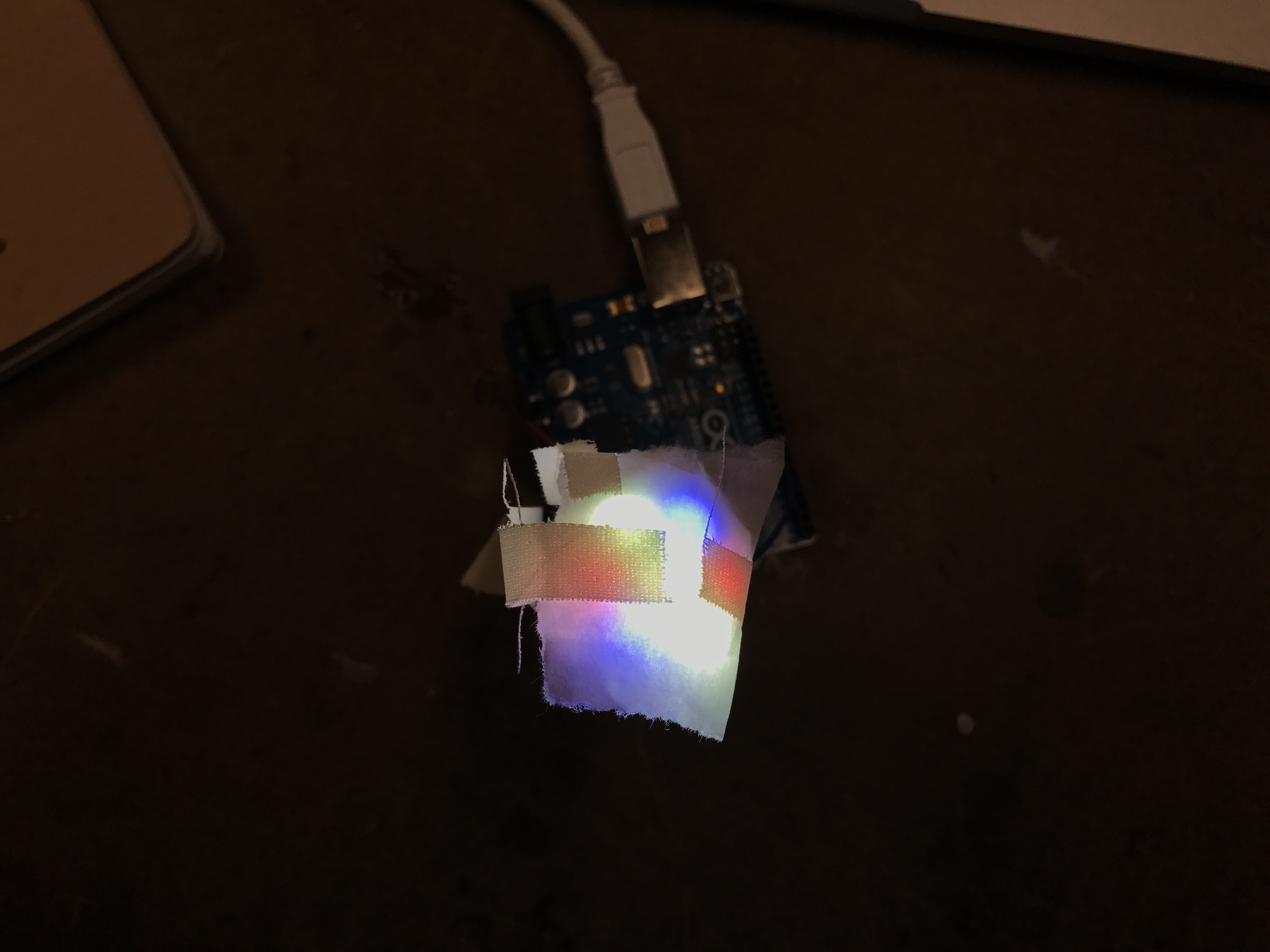
The board consists of 3 NeoPixel Jewels representing the stage lights. The far left neopixel has two slide potentiometer controls, one controlling green, one controlling red. The center neopixel acts as the white spot light. And the third, far right neopixel is controlled by two sliders, one red, one blue. There is also one sliding potentiometer acting as the master fader, and an on-off switch sits at the top that controls the boar’s power.

The Process
Circuitry
The first step was to get the lights up and running and test them out on a sliding potentiometer, starting with one, and then adding multiple.

Testing with sliders and RGB.
This is a modal window.
The next step was to add in the second and third neopixels and attach sliders to them.


This is a modal window.
This is a modal window.
Schematic


Code
Following the coding tutorial and examples from Adafruit and Tom Igoe, I was able to create a working program (after trial and error) to control the board and lights the way that I intended.
Challenge: I worked with a small button that I was trying to program as an on/off button. However, it was not able to be controlled by code in the way other buttons are with HIGH/LOW or state changes. It would work in turning on the board initially but then the potentiometers stopped working and the lights could not be altered, among other odd issues. Eventually after talking to others, it was decided to just connect this button directly to power and then to the board, so all power had to go through the button in order to reach the rest of the components – an analog HIGH/LOW.

| //https://learn.adafruit.com/adafruit-neopixel-uberguide/arduino-library | |
| //https://github.com/MakerDen/Maker-Den-NETMF/wiki/NeoPixel-Jewel-Setup | |
| //Tom Igoe, in class examples | |
| //http://cdn.sparkfun.com/datasheets/Components/Switches/SC608N-b10k.pdf | |
| //https://github.com/tigoe/NeoPixel_examples/blob/master/NeoPixelFadeAll/NeoPixelFadeAll.ino | |
| //---CODE---\\ | |
| // Parameter 1 = # of pixels in strip | |
| //Parameter 2 = pin number | |
| //Parameter 3 = pixel type flags | |
| const int numPixels = 7; | |
| const int neoPixelPin = 6; | |
| const int neoPixelPin2 = 10; | |
| const int neoPixelPin3 = 11; | |
| const int redRead = A5; | |
| const int greenRead = A4; | |
| const int blueRead = A2; | |
| const int red2Read = A1; | |
| const int whiteRead = A3; | |
| const int brightnessRead = A0; | |
| #include <Interval.h> | |
| #include <Adafruit_NeoPixel.h> | |
| Adafruit_NeoPixel strip_a = Adafruit_NeoPixel(numPixels, neoPixelPin, NEO_RGBW + NEO_KHZ800); | |
| Adafruit_NeoPixel strip_b = Adafruit_NeoPixel(numPixels, neoPixelPin2, NEO_RGBW + NEO_KHZ800); | |
| Adafruit_NeoPixel strip_c = Adafruit_NeoPixel(numPixels, neoPixelPin3, NEO_RGBW + NEO_KHZ800); | |
| void setup() { | |
| Serial.begin(9600); | |
| strip_a.begin();//initialize strip | |
| strip_b.begin(); | |
| strip_c.begin(); | |
| strip_a.clear(); //turn off LEDs | |
| strip_b.clear(); | |
| strip_c.clear(); | |
| strip_a.show(); //initialize pixels to off; not necessary, just thorough | |
| strip_b.show(); | |
| strip_c.show(); | |
| } | |
| void loop() { | |
| int redSlide = analogRead(redRead); | |
| int greenSlide = analogRead(greenRead); | |
| int blueSlide = analogRead(blueRead); | |
| int red2Slide = analogRead(red2Read); | |
| int whiteSlide = analogRead(whiteRead); | |
| int brightSlide = analogRead (brightnessRead); | |
| int red = map(redSlide, 0, 1023, 0, 255); | |
| int green = map(greenSlide, 0, 1023, 0, 255); | |
| int blue = map(blueSlide, 0, 1023, 0, 255); | |
| int red2 = map(red2Slide, 0, 1023, 0, 255); | |
| int white = map(whiteSlide, 0, 1023, 0, 255); | |
| int brightness = map(brightSlide, 0, 1023, 0, 255); | |
| Serial.println(red); | |
| strip_a.setBrightness(brightness); | |
| strip_b.setBrightness(brightness); | |
| strip_c.setBrightness(brightness); | |
| for (int pixel = 0; pixel < numPixels; pixel++) { | |
| // Serial.print("pixel "); | |
| //Serial.println(pixel); | |
| strip_a.setPixelColor(pixel, green, red, 0, 0); | |
| strip_b.setPixelColor(pixel, 0, red2, blue, 0); | |
| strip_c.setPixelColor(pixel, 0,0,0,white); | |
| } | |
| strip_a.show(); | |
| strip_b.show(); | |
| strip_c.show(); | |
| delay (30); | |
| } |
 by
by
Fabrication
The fabrication focused on both the housing for the lighting controller and for the stage structure.
The Lighting Controller


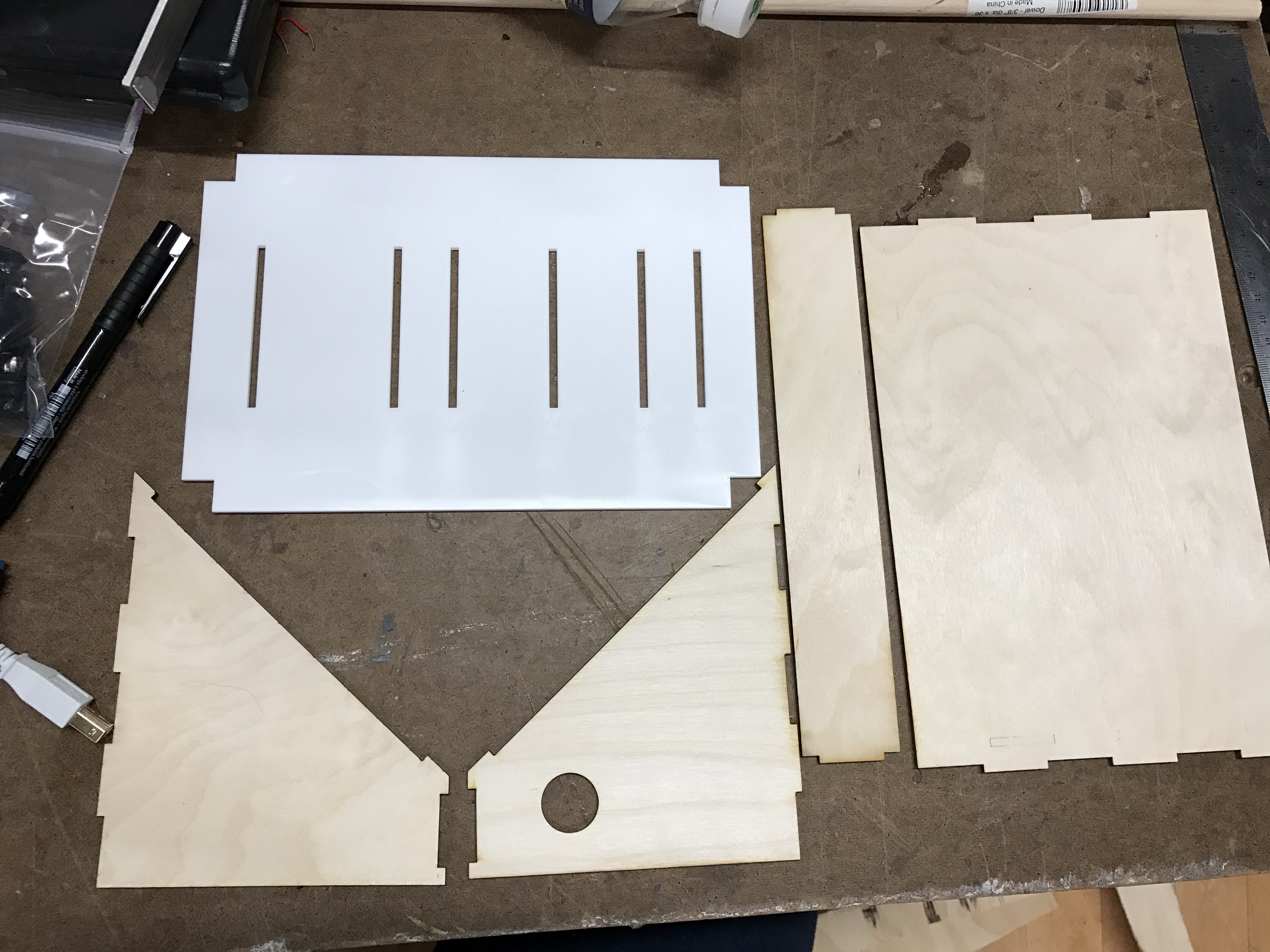
Challenges: The measurements were off with the first cut of the acrylic. I had to remeasure based on the wood pieces. The second cut of the plastic did not fit perfectly into the top of the wood pieces. I had to manually cut off a bit of the wood. The wood pieces were actually too loose together, and instead of snapping into place I had to hot-glue from the inside.
Putting the Circuitry Into the Casing

Challenges: The next step was to solder the board together. This was the part of the process where the board went from working to “It was working before but…” Round 1 of soldering left the lights flickering. Round 2 was also a failure. I believe this had to do with my soldering job not working well with the proto board I was using. Solder 3 worked like a charm. I used a prefab Adafruit perma board with the same layout as a breadboard. It worked on the first go (very lucky).


The Stage


Challenges: While designing the stage in Illustrator, I misjudged the size wood I had set aside in the shop (memory can be a funny thing). I thought I had 4×4 plywood. Turns out it was 4×2. I had to restructure the sizes, and limit the number of pieces that I cut. I removed the back board completely. While sending this through the CNC machine, the cut time was several hours more than manageable, so I scaled back again, and decided to use the band saw to cut the corner support poles.
The wood on the CNC machine presented its own series of challenges. The wood was buckled, so while setting the z location, the corners and the center were about 1/4″ off. This caused some of the pieces to not be cut through completely, and resulted in having to chip away around the edges. Also, the base board on the CNC was too chipped away at, and did not help with the buckled wood situation. The square with squares in it, in the design above, was to be the top of the stage, a frame-like structure with pockets to hold the lights. Due to the 1/4″ discrepancy, the pockets were not complete, and the center rectangles could not be removed completely. I had to remove this piece of the stage from the final set up.


All Together
Putting it all together was where I needed to improvise. Without the top frame structure, I used criss-crossed dowels to hang the lights from. Instead of wooden walls, I used black fabric (that somehow I cut about 1-2 inches too short).
Challenges: The wires that I cut and soldered for the lights from the control box were a bit short. I should have made them a foot longer in order for the lights to be placed within the stage and the control board to sit out front behind a potential audience. Instead, I set the lights in place and ran the wires to the box that has to sit directly on the side of the
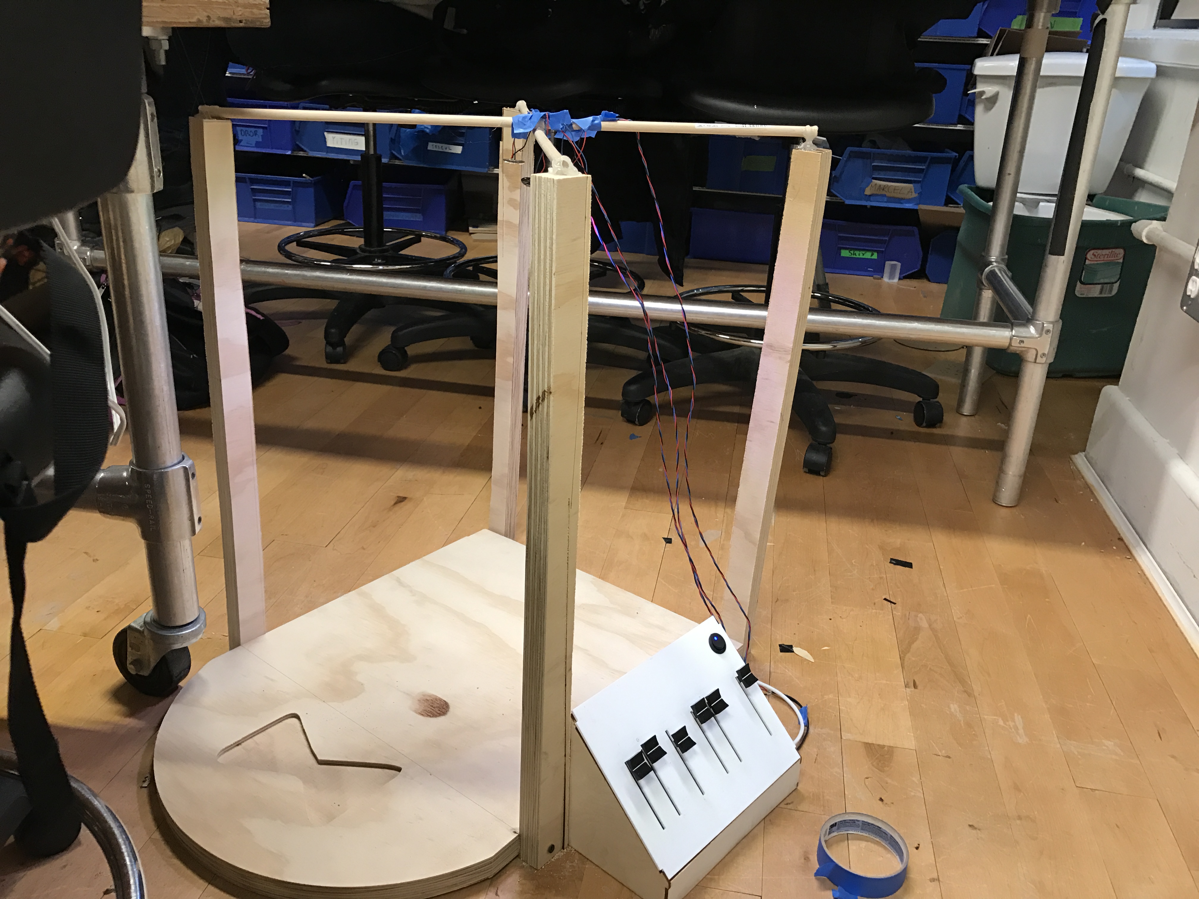


The final touch included adding a 9V battery back to the Arduino. And alas, it came together as a working stage and lighting control board!


Leave a Reply