
Design Challenge: Create a game controller that uses HID output, controls w, s, a, d keyboard presses, and comes together to play Atari’s Lunar Landing.
Video Player is loading.This is a modal window.
The media could not be loaded, either because the server or network failed or because the format is not supported.
This is a modal window.
The Controller
This game controller was designed both programmatically and physically to play the Lunar Landing game by Atari. While designing this controller, I took several things into account:
1) What is the most natural interface one would want to interact with when landing a spacecraft on the moon (or anywhere that one might need to land, gravity pending)?
2) What details can I add to make the user know that the controller is responding? #surpriseanddelight
3) What is the most efficient housing I could make for the motions needed for the controller-user movements?
The Process
Step 1: Programming the Buttons & Potentiometer
My initial inclination, taking the “most natural interface” was to use buttons for up and down and to use a potentiometer for right and left steering, like a car. Instead of a joystick, this prototype broke it down into two tangible experiences – that of left/right turning and that of up/down pressing.


Troubleshooting: After testing, reprogramming, adjusting the numbers for the potentiometer and more testing, the potentiometer proved to be undesired as an input device. The results were slow when interfacing with the game, and the landing craft took too long to turn in comparison to the actual button presses. Perhaps this was due to having too much resistance.
While troubleshooting the up/down button presses, there were times when the button presses would work in every application except in the Lunar Lander game interface. I played around with the code and upon removing the delays, the buttons worked just fine in the game interface. This makes me conclude that delays slow down the immediate response needed to make the landing module move efficiently.
Step 2: Finalizing the Code
I turned the potentiometer into 4 buttons – up(w), down(s), left(a), and right (d).


This is a modal window.
Responding to my second question, I added two more buttons – one to reload the page to restart the opening page of the game (command+r) and the other to press enter so the user can start the game (ASCII 176/enter key). Each time these two keys are pressed, an LED lights up to inform the user that their input has been accepted.
This is a modal window.
More Troubleshooting: The controllers not responding to the game became a topic of conversation around the shop. I had been using the Keyboard.write(); for most of the buttons outside of the Reload button.
<if (up == LOW) {

Keyboard.write('w');

Serial.println("UP");

}>
However, even with the delays removed, the controller did not work as smoothly as the WASD and up/down/left/right keys. It was discussed that in an email, Tom Igoe suggested using Keyboard.press/release. So I decided to just switch all of the buttons for that code to that command, added a minor delay, and had better, smoother results with movement.
Code
| //step 1: add url for board | |
| //Step 2: go to Board manager find and set board | |
| //step 2: include keyboard library | |
| //step 3: code! Reference - Tom Igoe - https://www.arduino.cc/en/Tutorial/KeyboardAndMouseControl | |
| //https://learn.adafruit.com/adafruit-feather-m0-adalogger/setup | |
| //https://learn.adafruit.com/adafruit-feather-m0-adalogger/adapting-sketches-to-m0 | |
| //https://itp.nyu.edu/physcomp/labs/labs-arduino-digital-and-analog/analog-in-with-an-arduino/ | |
| //https://www.arduino.cc/en/Reference/KeyboardPress | |
| //https://itp.nyu.edu/physcomp/labs/labs-arduino-digital-and-analog/digital-input-and-output-with-an-arduino/ | |
| //----------CODE--------- | |
| #include <Keyboard.h> | |
| const int upButton = 13; | |
| const int downButton = 12; | |
| const int leftButton = 11; | |
| const int rightButton = 10; | |
| const int reloadButton = 9; | |
| const int enterButton = 6; | |
| const int ledPin = 5; | |
| //int potMove; | |
| int up; | |
| int down; | |
| int left; | |
| int right; | |
| int reload; | |
| int enter; | |
| int led; | |
| void setup() { | |
| Serial.begin (9600); //set up serial baud rate | |
| pinMode(upButton, INPUT_PULLUP); | |
| pinMode(downButton, INPUT_PULLUP); | |
| pinMode(leftButton, INPUT_PULLUP); | |
| pinMode(rightButton, INPUT_PULLUP); | |
| pinMode(reloadButton, INPUT_PULLUP); | |
| pinMode(enterButton, INPUT_PULLUP); | |
| pinMode(ledPin, OUTPUT); | |
| Keyboard.begin(); | |
| } | |
| // | |
| void loop() { | |
| up = digitalRead(upButton); | |
| down = digitalRead(downButton); | |
| left = digitalRead(leftButton); | |
| right = digitalRead(rightButton); | |
| reload = digitalRead(reloadButton); | |
| enter = digitalRead(enterButton); | |
| //potMove = analogRead(A2); | |
| // led = digitalRead(ledPin); | |
| //use buttons and pot to control keyboard | |
| // Serial.println(potMove); | |
| if (up == LOW) { | |
| Keyboard.press('w'); | |
| Serial.println("UP"); | |
| delay(10); | |
| Keyboard.release('w'); | |
| } | |
| if (down == LOW) { | |
| Keyboard.press('s'); | |
| Serial.println("DOWN"); | |
| delay(10); | |
| Keyboard.release('s'); | |
| } | |
| if (right == LOW) { | |
| Keyboard.press ('d'); | |
| Serial.println("RIGHT_"); | |
| delay(10); | |
| Keyboard.release('d'); | |
| } | |
| if (left == LOW) { | |
| Keyboard.press('a'); | |
| Serial.println("LEFT_"); | |
| delay(10); | |
| Keyboard.release('a'); | |
| } | |
| if (reload == LOW) { | |
| Keyboard.press(135); | |
| Keyboard.press('r'); | |
| delay(50); | |
| Keyboard.releaseAll(); | |
| digitalWrite(ledPin, HIGH); | |
| delay(1000); | |
| Serial.println("RELOAD"); | |
| digitalWrite(ledPin, LOW); | |
| } | |
| if (enter == LOW) { | |
| Keyboard.write(176); | |
| digitalWrite(ledPin, HIGH); | |
| delay(1000); | |
| digitalWrite(ledPin, LOW); | |
| Serial.println("ENTER"); | |
| } | |
| // delay(1); | |
| // if (up == LOW) { | |
| // Serial.println("UP"); | |
| // } | |
| // | |
| // if (down == LOW) { | |
| // Serial.println("DOWN"); | |
| // } | |
| // | |
| // if (left == LOW) { | |
| // Serial.println("LEFT"); | |
| // } | |
| // | |
| // if (right == LOW) { | |
| // Serial.println("RIGHT"); | |
| // } | |
| // if (potMove <= 127) { | |
| // Serial.println("RIGHT"); | |
| // } | |
| //if (potMove >= 823) { | |
| // Serial.println("LEFT"); | |
| // } | |
| //delay(500); | |
| } |
 by
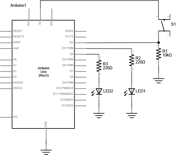
by Schematic


Fabrication
Materials:
24″ x 3″ Walnut wood
5 big red buttons
2 small buttons
wires
bread board
proto-board
acrylic
handle
Step 1: Solder Board Together


Testing the buttons along the way:
Step 2: Design and Fabricate the Housing

From the initial drawings came the Adobe Illustrator housing designs.


And for the acrylic lid:

 Troubleshooting: It was at this step that I realized it would have been better to have put the buttons into the casing before soldering. So in order to account for this error in post, I cut spacers with the engraved titles to put between the black top and the buttons.
Step 3: Put It All Together


References
Tom Igoe – https://www.arduino.cc/en/Tutorial/KeyboardAndMouseControl
https://learn.adafruit.com/adafruit-feather-m0-adalogger/setup
https://learn.adafruit.com/adafruit-feather-m0-adalogger/adapting-sketches-to-m0
https://itp.nyu.edu/physcomp/labs/labs-arduino-digital-and-analog/analog-in-with-an-arduino/
https://itp.nyu.edu/physcomp/labs/labs-arduino-digital-and-analog/digital-input-and-output-with-an-arduino/
https://www.arduino.cc/en/Reference/KeyboardPress
https://itp.nyu.edu/physcomp/wp-content/uploads/LabDigitalInOut_schem.png
Leave a Reply