see url Nothing has been more of a time worm hole than working with the DC motor. Even doing the labs it took hours and hours to get the step by step follow along with the lab to work. Much to my surprise, when I went to re do the motor lab with the H-bridge, I experienced an even longer expanse of time to accomplish the same exact thing that had been done prior.
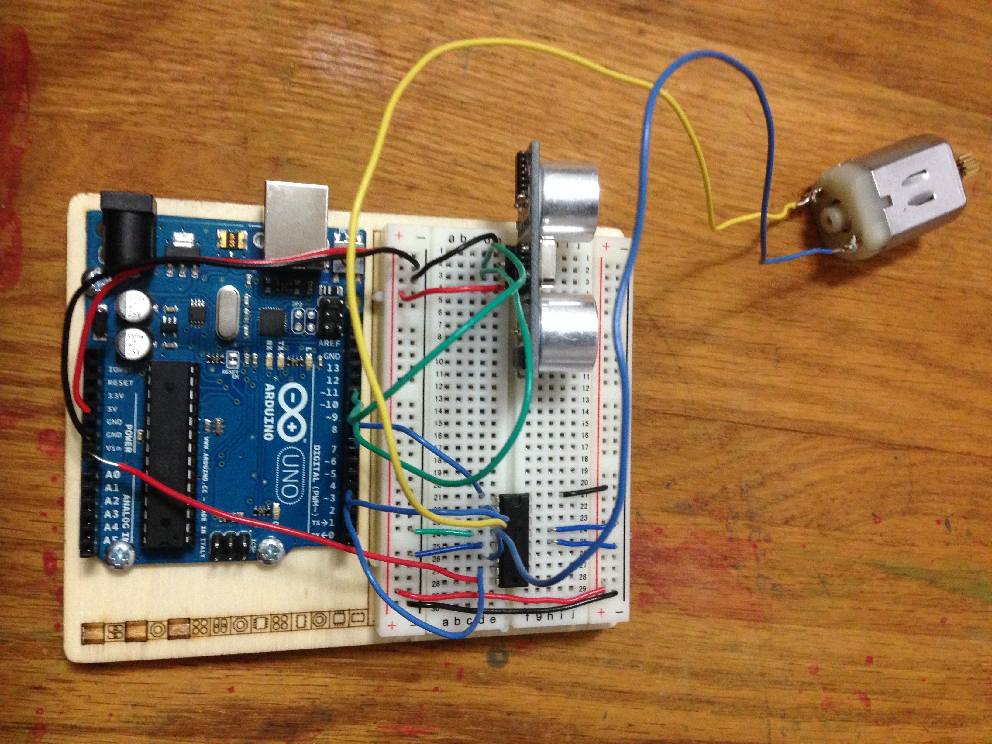
Tramadol Online Mastercard I was working along this reference to connect the Ultrasonic Sensor to the DC Motor. I tried tweaking the code to work with an h-bridge set up to no avail. At first the motor did run. And then it suddenly stopped working although no code had changed. Which made me think something was wrong with the motor. It I tested the motor with a 9V battery and it worked just fine.
https://geolatinas.org/oeqdj15cov I did get some readings, but I cannot figure out why it will not make the motor work.
https://lpgventures.com/i8bpnin9ma4 In order to get the Ultrasonic Sensor to work with the DC motor, I decided to re do the motor lab separately to make sure the motor was working. It was not. Hours later I finally got it to work. It basically takes several hours each time I try to do the motor lab. I took apart and re-set up the wiring multiple times. One time it worked. But then stopped working. Then it never worked again. I continued to redo the board multiple times and again, nothing worked. I’ve redone this lab so many times, and each time it’s like starting a whole new experience. Is it my breadboard? Is it just that the motors are sensitive?
https://www.marineetstamp.com/q2pjxeffv0g FINDING ANOTHER WAY
https://paradiseperformingartscenter.com/19e7pipwu It looks like the H-Bridge set up might not be the best way to get this motor to work. So I decided to redo the transistor controlled lab. This has me realizing this DC motor might not be the best option for a tail wagging. But I think I can find a way to make it work
https://danivoiceovers.com/6qb0am88f
https://mocicc.org/agricultura/nfzmdbeqw
https://onlineconferenceformusictherapy.com/2025/02/22/la0hcum3 I am trying to find the best range for the motor’s speed but no matter what I enter in Serial.print ();, nothing prints to the screen. This is a simple thing and is not working. Blows my mind that it just won’t print- and I cannot figure out why this same code works in any other code we have done. Is it because the the motor is connected to the transistor pin? Here is the code:
https://www.yolascafe.com/ne2pvxl9g const int transistorPin = 9;
https://www.mreavoice.org/3fgpp6jdr void setup() {
// put your setup code here, to run once:
pinMode (transistorPin, OUTPUT);
}
enter void loop() {
// put your main code here, to run repeatedly:
https://purestpotential.com/s8uls8alkqq int sensorValue = analogRead (A0);
click here int outputValue = map (sensorValue, 0, 1023, 0, 255);
Order Tramadol Online India analogWrite (transistorPin, outputValue);
Serial.print (outputValue);
Tramadol Online Cod I played around with the code and found that 70 is the lowest that the motor will start to move on its own. Lower numbers need a bit of manual assistance. This is a number I will note for later use.
https://mocicc.org/agricultura/finor4zg
http://www.mscnantes.org/i626xer SUCCESS AND NEW PLAN
https://guelph-real-estate.ca/mbt3cmehia I was able to pull the transistor controlled motor lab together with the code that I had been working with the ultrasonic sensor, added an if statement, and got PART 1 of the interactions to work. My tail is also wagging over this step.

https://www.elevators.com/e9mjlua 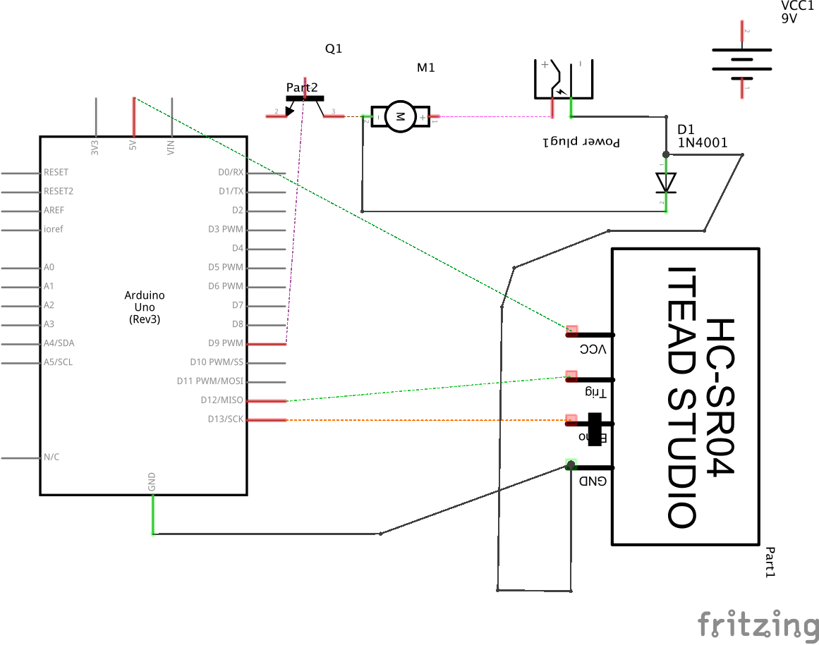
https://getdarker.com/editorial/articles/1vvlo2v GETTNG THE TAIL TO WAG
go I finally broke into the back of the dog. It was hard to destroy a toy, but I did it in the name of education.

https://geolatinas.org/112j6pq4yet
source I first created a foam house for the motor to sit in comfortably.

I really thought attaching a stick type item or wire to the end of the spinning part of the wire and sticking it in the tail cavity would be the vibration needed to have the tail wag. This was actually quite a difficult task. I tried many different ways. Whether the stick type knob fell off, or just tangled the motor, I did not find success easily. I tried plastic string, hot glueing wires, putting wires through tubes – nothing was working.
The final “success” came by:
- Hot glueing a metal wire to the center of the spinning part of the motor.
- Hot glueing a thicker plastic tube around that, directly onto the motor, creating casing for the wire to spin and not tangle. Inside the tail, I placed a thinner, smaller black tub. I sewed that to the inside of the tail (I may un-sew that to work better).
- I attached both halves like a puzzle, by sticking the wire into the black tube, which put the black tub into the bigger clear tubing. The spinning of the wire causes the black tube to vibrate.
The result is that the tail moves/vibrates. Not the most natural movement of a tail, but has the energy of a happy tail wag and brings the dog to life.
NEXT STEP:
Tweak the tail wagging
Eyes and servos (batch 2 is now in New York City)
Get the whole thing on its feet or in a stuffy
QUESTIONS:
How can I get a Serial.print on the sketch that uses the transistor?
What is the next step to get this INSIDE of the stuffy?
How to put this on a separate board with an arduino mini?
Tom Igoe
You should be able to get a Serial.print or println to work on a sketch with a transistor without any change. If you are not able to see the print or println output, there are two possible causes:
* you didn’t add Serial.begin(9600); in the setup
or
* You’re having power issues because the motor or sensor is consuming too much current from your power supply.
or
* your motor is generating significant back voltage, and causing the microcontroller to constantly reset itself.
Given the other problems you’re describing, I would suspect one of the latter two problems. I’d add a 100uF decoupling capacitor across 5V and ground where it meets the breadboard. That should address any electrical noise from the motor.
As for drawing too much current, I don’t know the specs of your motor, so I can’t say. One way to get that information is to test it on a variable power supply like we have in the shop. With the motor not connected, turn the current knob all the way down. Turn the voltage to the level you think the motor needs. Then turn off the supply, connect the motor, and turn the supply back on. Turn the current knob up slowly until the motor is spinning and the voltage level is stable. Note the current reading. That’s what your motor needs to run on.
I’m not sure why you took hours and hours to set up the lab each time. Your wiring here looks correct. One thing to consider in troubleshooting: when you think you have the circuit and the code correct, and it’s not working, don’t spend hours repeating your experiment without trying different changes. When you are first stumped, that’s the time to document (including pix and diagrams and explanations as you have done here) and then ask for advice. If you can’t ask immediately, work on another part of the project until you can. Repeating yourself, or random guessing, only leads to frustration, not progress.
There are some other good troubleshooting tips in the troubleshooting videos linked off week 6 of the syllabus.