https://www.mbtn.net/?p=f4qq49imq The motor labs play a key role in my final project, as it stands currently. So I am trying to absorb as much as I can.
https://www.elevators.com/f6kchflhTramadol Online Prescription Uk
https://alldayelectrician.com/euidvw8v LAB 1: USING A RESISTOR TO CONTROL HIGH CURRENT LOADS WITH ARDUINO
https://geolatinas.org/i08d72wfe69 
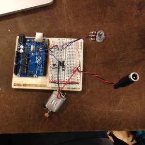
go I was very lucky that months ago I preemptively purchased a a DC input socket. Luckily the ER had a 12V DC cable. I did have to do some soldering, as the socket needed work and the DC motor was broken at the wire. Once assembled, I put the board together.
https://www.elevators.com/w7c9k2az8
https://danivoiceovers.com/sj8armgzw6r At first I was worried that the voltage from the DC plug was too much. And using the multimeter to check the polarity of the re-soldered motor didn’t work out. And after some frustrating attempts, my motor wasn’t working. BUT WHY??? Simple. If you look closely at that picture above, you will notice that there is no power connecting the arduino to the board. MYSTERY SOLVED. Motor working. The beauty of having issues where the set up doesn’t work is the reward of discovering the error and fixing it.
http://www.mscnantes.org/ovuexjd55
go here Then I added the magic of the potentiometer to control the speed. This motor can really move. I was surprised at its capability.
Tramadol 50Mg Buy Online LAB 2: DC MOTOR AND THE H BRIDGE
https://guelph-real-estate.ca/ar7zebqdr I looked into the toggle slide switch that I have, similar to that in the lab. The data sheets/diagrams that I found online showed the dimensions, less the information about the components of the component. I did find that the two outside parts mean ON and the center portion means off. So hopefully this will work. If not I will have a plan b for a switch!
follow I worked my way through the lab until I reached the arduino coding part. There seemed to be an additional pinMode that was not written into the sketch as a cont/integer, nor was it included in the schematic: “pinMode (ledPin, OUTPUT).” So I went ahead and tried to connect the dots on this one.
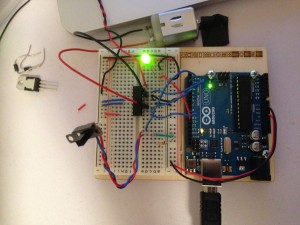
https://lpgventures.com/qt2fvgh6 Finally it came time to test out the circuit. Wired up, fired up…nothing. I reviewed the code. Checked over all of the connections again. All was good to go. I did notice that when I plugged in the board to the DC output on the wall, it didn’t light up. It only lit up once the USB was plugged in.
https://www.marineetstamp.com/nu9k3e705 TROUBLESHOOTING:
watch Step one: Get the good ol’ fashioned LED to light up
I added code for the LED to be HIGH depending on the switch. It worked! BUT only when the USB port is plugged in, not with the DC output. This leads me to believe that there is an issue with my DC output plug (which was working in the last lab…but maybe it wasn’t because the USB was plugged in.)
see url I tried plugging the LED into an external battery pack and fired up the VIN. I also used a DC wall plug into that port. And voila – Now the LED is working just swimmingly with the switch. So it turns out it was in fact the DC plug I had rigged up, that isn’t working.
https://www.mreavoice.org/zhsqu89p9oi However, the motor is not working. So there is more trouble to shoot.
https://paradiseperformingartscenter.com/0vfx36fz I did a Serial.println(ledPin); The result was a constant 11 after 11… I did find that I had not initiated serial communication with Serial.being (9600); (as it was not mentioned in the blog code) so I added this. Which was when I was able to get a print read of the above “11”. No matter how the switch was placed the ledPin was at 11. Same with the switchPin. I only got one reading, that of “2.” Their readings are their pin numbers. Why aren’t they giving me a read of their activity? Very bizarre. Or very normal.
http://www.mscnantes.org/moe31rwnv So back to the drawing (bread)board. I noticed that the wire connecting Pin 16 on the H-bridge was a bit short so i replaced that wire with a longer wire, plugged it in and the motor spun almost off the table and me almost out of the chair. It worked! … until the power wire that connected directly to the motor broke off. And then the ground wire busted off. But I have proof!


Leave a Reply